While organising to have some business cards printed for networking at an upcoming conference, I could not find anything which I thought were both professional and ‘geeky enough’. As a result, I did what any self-respecting geek would do: Attempted to over-engineer a ‘solution’ to a trivial problem.
This is the result.
The card came about while I was working on another project. While routing a few PCBs I thought I might see what an A8 sized PCB would look like for use as a business card… Which, to my partner’s dismay, is where the madness began.
The card itself could have been designed with only the silk-screen being used; however, this would have been a bit of a waste. As a result, I started thinking what would be a potentially useful wallet sized circuit. In the end, I went with a very simple MAX232 based RS232 to TTL / CMOS converter for the following reasons:
- It’s a very easy circuit to route, but provides a useful tool for hobbyists and engineers alike.
- Flashing lights aren’t really my bag.
- It has few components making it easy to solder up - in my case, left as an ‘exercise for the reader’.
My initial thoughts were that 1.6mm or 2.0mm FR4 may have been a bit too chunky for such an application. Luckily, the fab that I’ve been using provides both 0.8mm and 0.6mm FR4. However, I was concerned that 0.6mm might be a bit too thin and brittle for the application, so 0.8mm seemed like the go.
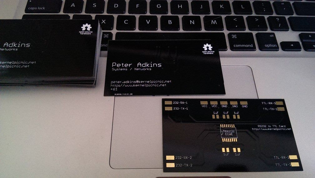
The front of the card simply contains my contact details, silk-screened onto the ‘top’ of the board. The circuit itself is on the rear of the card. Unfortunately, a few VIAs were required, which can be seen on the front of the card under the right light.
In order to get things working, all you’d need to do is solder on a MAX232ECWE, five 1uF SMD capacitors - I opted for 1210 SMD capacitors as 0603 parts are a pain to solder with a regular iron without a magnifying light or a good set of eyes. Finally, connect either bare conductors or test leads to the relevant RX/TX pairs, and supply 5VDC in at the VCC pin(s).
Although it might be a bit of ‘wank’, it has still provided a few hours of enjoyment and - in my opinion - looks pretty awesome.
The Eagle BRD and SCH files will be uploaded to GitHub and shared once I have confirmed that all is well with the boards and will be distributed under an OpenSource Hardware licence. Feel free to chop, change, or otherwise modify to your hearts content.